
Specifications, block diagram, example circuit, applications and FAQ
1. Introduction
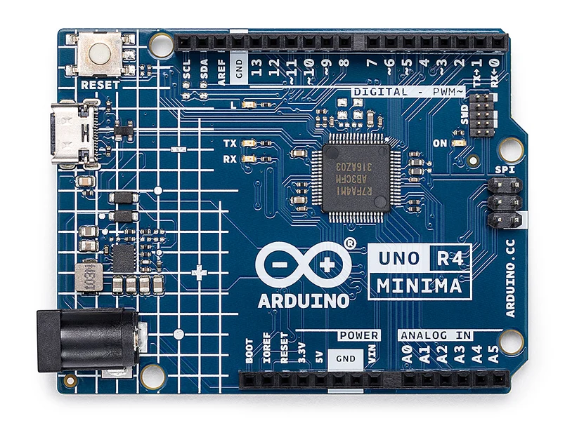
The Arduino UNO R4 Minima is the first UNO board built on a 32-bit microcontroller. Earlier UNO boards used an 8-bit AVR chip. The R4 Minima uses the Renesas RA4M1 (Arm Cortex-M4, 48 MHz), which brings more speed, more memory and new peripherals, while the board layout, 5 V logic and Arduino IDE workflow stay the same. For most users, this means a familiar UNO that is simply more capable.
2. Why Arduino Moved from the R3 to the R4
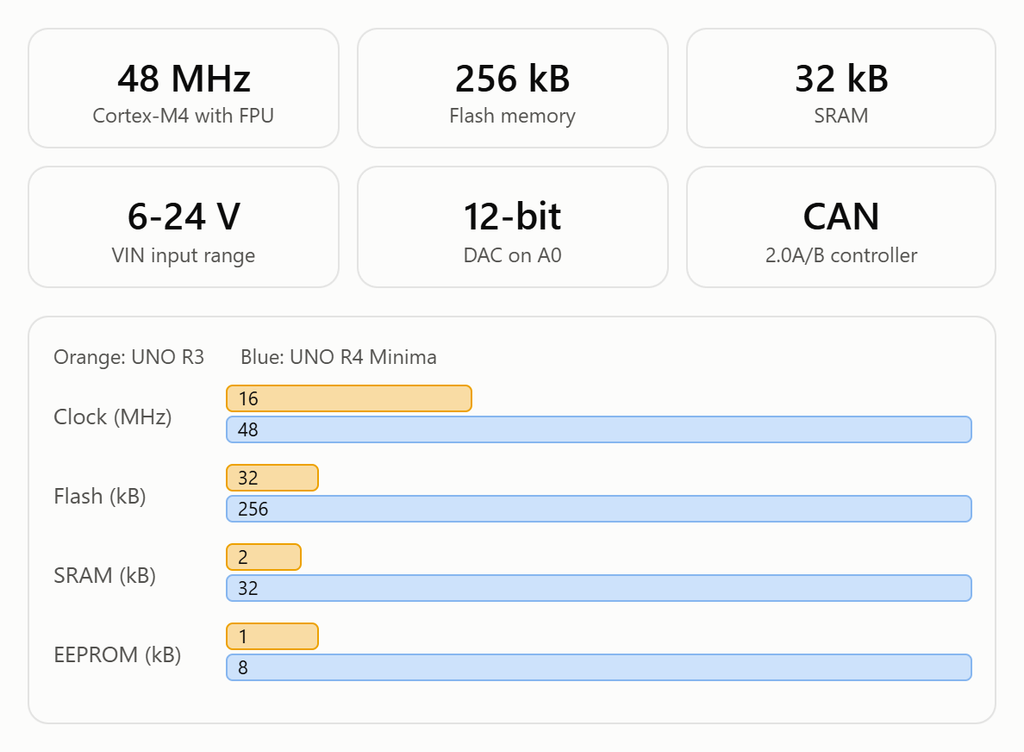
The UNO R3 used the ATmega328P, which has 32 kB of flash and only 2 kB of RAM. That became limiting for modern libraries, displays, sensor processing and communication stacks. The R4 Minima addresses this directly:
- Speed: 48 MHz instead of 16 MHz, plus a hardware floating-point unit for faster decimal math.
- Memory: 256 kB flash, 32 kB SRAM and 8 kB data flash, about 8x, 16x and 8x the R3 respectively.
- Connectivity: USB-C replaces USB-B, and a CAN controller is built in.
- Analog: a 12-bit DAC, an ADC that can run up to 14-bit, and an internal op-amp.
- Development: an SWD header for real hardware debugging.
Compatibility is kept deliberately. The pin layout and 5 V logic match the R3, so most existing shields and sensors work without changes.
3. Technical Specifications
| Parameter | Value |
| Board name / SKU | Arduino UNO R4 Minima / ABX00080 |
| Microcontroller | Renesas RA4M1 (Arm Cortex-M4 with FPU) |
| Clock speed | 48 MHz |
| Flash / SRAM / Data flash | 256 kB / 32 kB / 8 kB |
| Operating voltage | 5 V |
| Input voltage (VIN) | 6-24 V |
| Digital I/O pins | 14 |
| PWM pins | 6 (D3, D5, D6, D9, D10, D11) |
| Analog inputs | 6 (A0-A5) |
| DAC | 1 (12-bit, on A0) |
| Communication | UART, I2C, SPI, CAN 2.0A/B, USB 2.0 Full-Speed |
| DC current per I/O pin | 8 mA |
| USB connector | USB-C (programming and power) |
| Debug | SWD header |
| Dimensions | 68.85 mm x 53.34 mm |
4. Block Diagram Explained
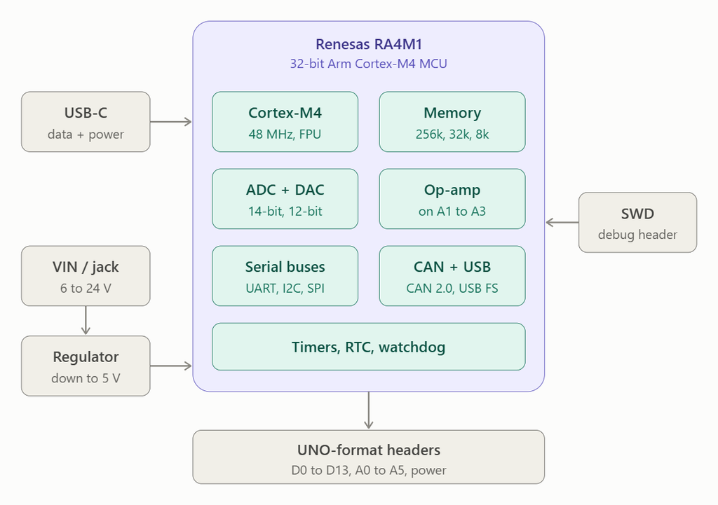
Power path. The board can be powered over USB-C (5 V) or through VIN/the barrel jack (6-24 V). Voltage from VIN passes through the onboard regulator, which brings it down to 5 V for the board. The higher the input voltage and the load current, the more heat the regulator dissipates, so a supply in the 7-12 V range is a safe choice for most projects.
The RA4M1 microcontroller contains almost everything the board does:
- Cortex-M4 core with FPU runs your sketch at 48 MHz.
- Memory holds the program (flash), working variables (SRAM) and saved settings (data flash, used like EEPROM).
- ADC and DAC read analog signals and produce a true analog voltage output on A0.
- Op-amp is exposed on A1 (+), A2 (-) and A3 (output) for signal conditioning.
- Serial buses provide UART, I2C and SPI for sensors, displays and modules.
- CAN and USB give industrial and automotive networking plus native USB, including keyboard and mouse emulation.
- Timers, RTC and watchdog handle PWM, timekeeping, scheduling and automatic recovery from lock-ups.
Board interfaces. The chip connects to the UNO-format headers (D0-D13, A0-A5 and power pins). The SWD header is used for external debugging.
5. Feature Details
Processor and FPU. The Cortex-M4 core is a 32-bit design, and 32-bit arithmetic is much more efficient than 8-bit. The FPU accelerates floating-point calculations such as filtering, PID control and sensor fusion.
Memory. With 256 kB of flash, larger sketches and libraries fit comfortably. The 32 kB of SRAM supports bigger buffers, display data and communication stacks. The 8 kB of data flash stores calibration values and user settings that must survive power loss.
USB-C and native USB. The USB-C port connects to the chip’s own USB controller. It is used for uploading code, serial monitoring and power, and it lets the board act as a keyboard, mouse or other HID device.
Power input. The 6-24 V VIN range lets the board share a supply with motors, LED strips and other actuators. Check regulator heating whenever the board powers other circuits.
5 V logic. Although the RA4M1 can run at other voltages, the Arduino design runs the board at 5 V so older UNO shields and circuits keep working. All pins are 5 V except the 3.3 V pin.
DAC. The 12-bit DAC on A0 outputs a real analog voltage for audio, waveforms and analog control signals. This is cleaner than filtering PWM.
ADC. The analog inputs default to 10-bit for R3 compatibility, but the hardware supports up to 14-bit. Raise it with analogReadResolution() in your sketch.
Op-amp. The internal op-amp amplifies small sensor signals without needing an external amplifier chip.
CAN bus. The built-in CAN 2.0A/2.0B controller uses D4 (CANTX) and D5 (CANRX). Connect it to a CAN transceiver such as the MCP2551 or TJA1050 and add proper bus termination.
Timers, RTC and watchdog. General-purpose and asynchronous timers drive PWM and scheduling, the RTC keeps time and the watchdog restarts the system if software hangs.
SWD debugging. An external debugger over SWD gives you breakpoints and step-through execution, which is far more productive than print-statement debugging.
6. Pin Reference
| Pin | Functions |
| D0 / D1 | UART RX / TX |
| D3, D5, D6, D9, D10, D11 | PWM output |
| D4 / D5 | CAN TX / CAN RX |
| D10-D13 | SPI (CS, MOSI, MISO, SCK) |
| D13 | Onboard LED |
| A0 | Analog input and 12-bit DAC output |
| A1 / A2 / A3 | Op-amp (+) / (-) / output |
| A4 / A5 | I2C SDA / SCL |
| VIN | 6-24 V supply input |
Each I/O pin supplies at most 8 mA, so drive relays, motors and large LEDs through a transistor, MOSFET or driver module.
7. Example Circuit
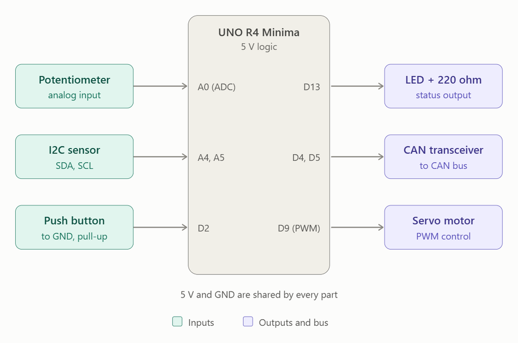
This circuit shows how common parts connect to the board:
- Potentiometer to A0: the wiper goes to A0, and the outer legs go to 5 V and GND. Read it with analogRead(A0).
- I2C sensor to A4 / A5: SDA goes to A4 and SCL to A5, with 5 V and GND. Check that the sensor module is 5 V compatible.
- Push button to D2: one side goes to D2 and the other to GND. Use INPUT_PULLUP in code.
- LED to D13: connect through a 220 ohm resistor to GND.
- CAN transceiver to D4 / D5: TX goes to D4 and RX to D5, then to the CAN bus lines.
- Servo on D9: use the PWM output on D9, but power the servo from a separate supply when it draws more current than the board can provide.
All parts share the same GND with the board.
8. Getting Started
- Install the latest Arduino IDE.
- Open Boards Manager and install Arduino UNO R4 Boards.
- Connect the board using a USB-C data cable.
- Select Arduino UNO R4 Minima as the board and choose its port.
- Open File > Examples > 01.Basics > Blink and click Upload.
If the board is not detected, try another cable (some are charge-only) or a different USB port. Double-pressing the reset button puts the board into bootloader mode.
9. UNO R3 Compatibility
Shields and sensors using standard 5 V UNO connections generally work as-is. Most sketches using standard Arduino functions (digitalWrite, analogRead, Serial, Wire, SPI) also run unchanged. Code that accesses AVR registers directly or uses AVR-only libraries must be adapted, because the processor architecture is different.
10. End-Use Applications
- Education and STEM: a classroom board with a huge ecosystem of tutorials, plus enough power to teach floating-point math, DAC output and CAN networking.
- Robotics: PWM outputs and fast processing for motors, servos and sensor fusion.
- Automotive and industrial networking: CAN-based data readers, gateways and monitors.
- Audio and signal generation: tone, waveform and simple synthesizer projects using the DAC.
- USB HID devices: custom keyboards, macro pads, game controllers and accessibility tools.
- Sensor monitoring and data logging: environmental, energy and agricultural loggers using I2C/SPI sensors, an SD card and the RTC.
- Home automation and IoT nodes: sensor and control nodes, with an external module added for wireless connectivity.
- Prototyping and product development: quick proof-of-concept builds using standard UNO shields.
- Test and measurement: data acquisition and sensor calibration using the higher-resolution ADC and DAC.
11. Frequently Asked Questions
1. What is the Arduino UNO R4 Minima?
A 32-bit UNO-format development board based on the Renesas RA4M1 (Arm Cortex-M4, 48 MHz). It is the base model of the UNO R4 family.
2. How is it different from the UNO R4 WiFi?
Both use the same RA4M1 chip and form factor. The WiFi version adds an ESP32-S3 module for Wi-Fi and Bluetooth, a 12×8 LED matrix and a Qwiic connector. The Minima has no wireless features and is the simpler, lower-cost option.
3. Is it compatible with UNO R3 shields?
Yes, in most cases. The layout and 5 V logic are the same. Shields that depend on AVR-specific features may need code changes.
4. Will my old sketches work?
Most sketches using standard Arduino functions (digitalWrite, analogRead, Serial, Wire, SPI) do. Sketches that use AVR registers directly or AVR-only libraries need to be updated.
5. What voltage does it run on?
5 V logic. It can be powered by USB-C (5 V) or by VIN/barrel jack with 6-24 V.
6. How much current can each pin supply?
8 mA per I/O pin. Use a driver circuit for anything that needs more, such as motors, relays or large LEDs.
7. Does it have Wi-Fi or Bluetooth?
No. Use the UNO R4 WiFi or add an external module.
8. Can the DAC drive a speaker?
Not directly. The DAC output can feed an audio amplifier, which then drives the speaker.
9. How do I use CAN?
Connect a CAN transceiver to D4 (TX) and D5 (RX), use the Arduino CAN library for the R4, and terminate the bus properly (typically 120 ohm at each end).
10. What is the ADC resolution?
The default is 10-bit for R3 compatibility. Use analogReadResolution(12) or analogReadResolution(14) for higher resolution; the hardware supports up to 14-bit.
11. Can it act as a USB keyboard or mouse?
Yes, through its native USB support and the standard Keyboard and Mouse libraries.
12. How do I debug code on the board?
Use the SWD header with an external debugger for breakpoints and step-through debugging. Serial printing also works.
13. Which software can I use?
Arduino IDE 2.x, Arduino Cloud Editor and Arduino CLI. Install the Arduino UNO R4 Boards package from the Boards Manager.
14. My computer does not detect the board. What should I do?
Use a USB-C data cable (some cables are charge-only), try another port, restart the IDE, and double-press the reset button to enter bootloader mode.
15. Is the board open source?
Arduino publishes schematics, pinouts and documentation for it. Check the Arduino documentation site for current files and license terms.
16. Who is it best for?
Beginners who want the classic UNO with better performance, educators who want a durable classroom board, and makers who need CAN, a DAC or more memory without changing board format.
12. Conclusion
The Arduino UNO R4 Minima keeps what made the UNO popular: the familiar layout, 5 V logic, a large community and an easy IDE. It modernizes the core with a 48 MHz 32-bit Cortex-M4, 256 kB of flash, 32 kB of SRAM, a 12-bit DAC, CAN bus, USB-C and SWD debugging. It is a practical upgrade path from the UNO R3.