
A breadboard is a reusable board that lets you build and test electronic circuits without any soldering. You push component legs and jumper wires into small holes, and hidden metal strips under the holes connect them. If you make a mistake, you pull the part out and try again. This guide explains how a breadboard is wired inside, how to place components correctly, and how to build six basic circuits: an LED circuit, a push-button circuit, series and parallel LEDs, a voltage divider, a transistor switch and a 555 timer LED blinker. It includes diagrams, tables, common mistakes and a detailed FAQ.
What Is a Breadboard?
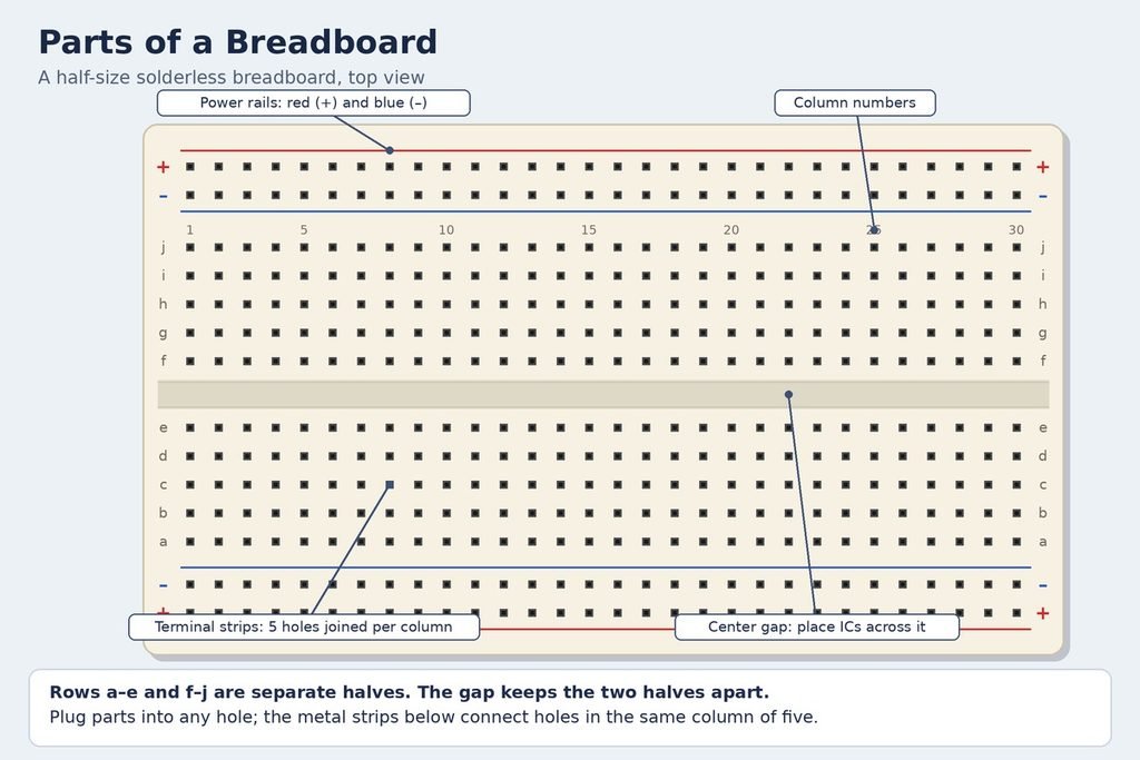
A solderless breadboard is a plastic board with a grid of holes. Under the holes are spring metal clips that grip component legs and pass the signal along a strip. The holes are spaced 2.54 mm (0.1 inch) apart, the same spacing as the pins of standard ICs, headers and many modules.
The name “breadboard” comes from early radio builders who nailed components to a wooden bread-cutting board. Today the word means the plastic solderless version used for prototyping, learning and testing.
A breadboard is a reusable board for building electronic circuits without soldering. You push component legs and jumper wires into small holes, and hidden metal strips underneath connect them. If you make a mistake, you pull the part out and try again, which makes it the best starting tool for learning electronics.
Why beginners use a breadboard
- No soldering iron or special tools needed
- Parts can be reused in many projects
- Easy to change a circuit and test again
- Safe for low-voltage experiments
Common breadboard sizes
| Type | Tie Points | Best For |
|---|---|---|
| Mini | 170 | Tiny, single-part tests |
| Half-size | 400 | Most beginner circuits |
| Full-size | 830 | Larger projects with ICs |
Terminal strips (the main area)
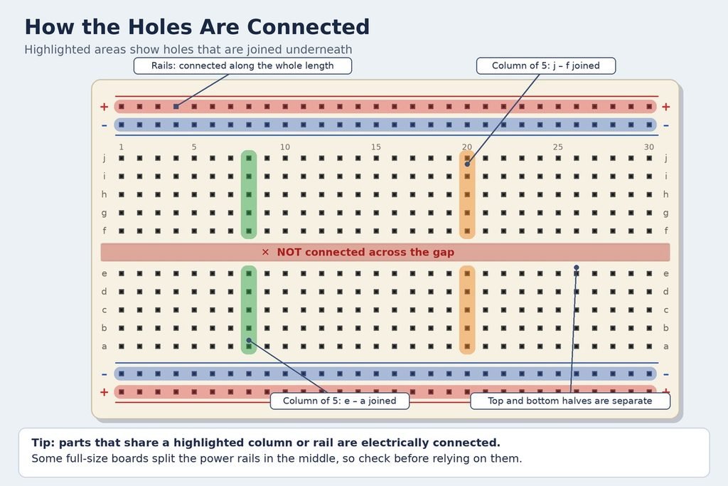
Each column of five holes (a–e, and f–j) is connected. Plug two parts into the same column of five and they are electrically joined.
Power rails (the long side lines)
The long lines marked red (+) and blue (–) run the length of the board. Connect your battery or supply here, then pick up power from any hole along the rail.
The center gap
The gap separates the top and bottom halves. It lets you place chips (ICs) across it so each pin gets its own column.
Quick tips
- Some full-size boards have power rails split in the middle, so check before you trust them
- Use red wires for positive and black or blue wires for negative
- Never plug both legs of one part into the same column of five
Parts you need to get started
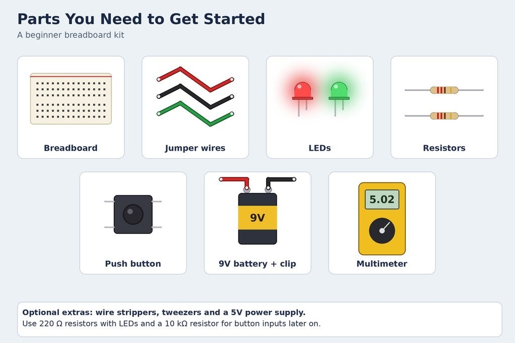
- Breadboard (half-size is fine)
- Jumper wires (male-to-male)
- 9V battery with clip, or 5V supply
- LEDs (red or green)
- Resistors (220 Ω and 10 kΩ)
- Push button
- Multimeter (optional but helpful)
How to insert parts correctly
- Push legs straight down, gently
- Trim or bend long legs so they stay neat
- Use short wires so the circuit is easy to read
- The longer LED leg is positive (anode); the shorter leg is negative (cathode)
Basic Circuit 1: Light an LED
This is the “hello world” of electronics.
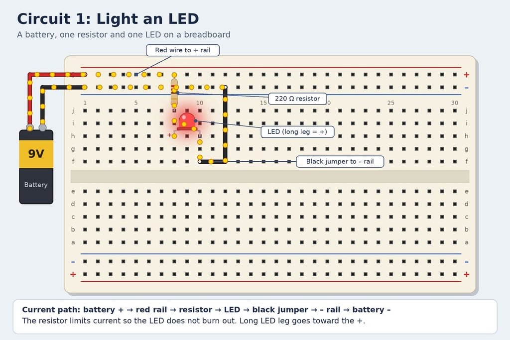
You need: one LED, one 220 Ω resistor, a battery or 5V supply, and two jumper wires.
- Connect the battery’s positive wire to the red rail and negative to the blue rail.
- Place the resistor from the red rail to a column in the top half.
- Put the LED’s long leg in the same column as the resistor, and its short leg in a column two holes to the right.
- Run a jumper wire from the short leg’s column to the blue rail.
- Switch on the power. The LED should glow.
Why the resistor matters
An LED has almost no resistance of its own. Without a resistor, too much current flows and the LED can burn out quickly.
If it doesn’t light
- Turn the LED around, as it may be backwards
- Check that the LED legs sit in different columns
- Make sure the power rails are connected to the battery
Basic Circuit 2: Control an LED with a Push Button
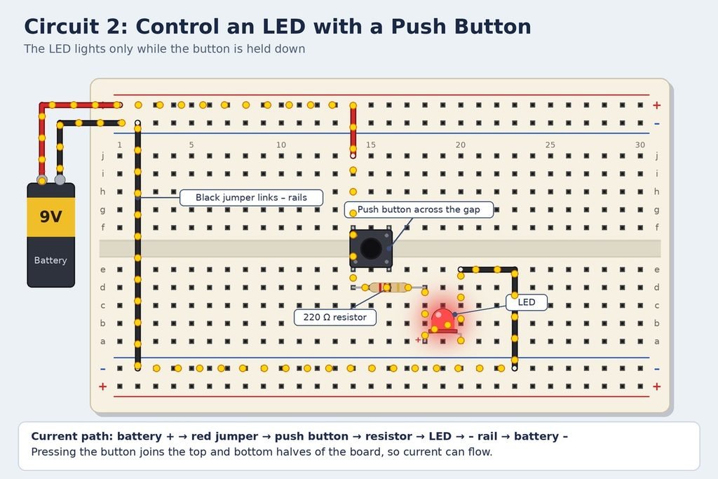
You need: one LED, one 220 Ω resistor, one push button, a supply, and jumper wires.
- Connect the battery to the top rails, then link the two blue rails with a black jumper.
- Place the push button across the center gap.
- Run a red jumper from the red rail to the button’s top-half column.
- Connect a resistor from the button’s bottom-half column to the LED’s long leg.
- Connect the LED’s short leg to the bottom blue rail with a jumper.
- Press the button. The LED lights while you hold it and goes off when you let go.
How it works
The button is a switch. Pressing it joins the top and bottom halves so current can flow. Releasing it opens the circuit and stops the flow.
Basic Circuit 3: Two LEDs in Series and in Parallel
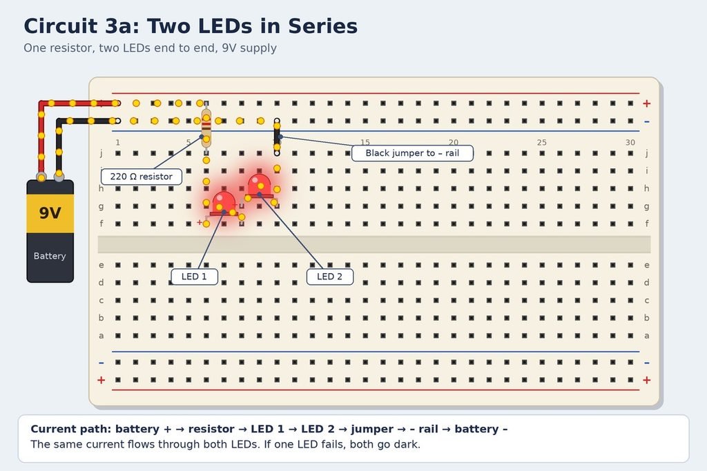
Series (one after another)
Connect the LEDs end to end, then add one resistor. The same current flows through both, but they need a higher supply voltage (around 9V).
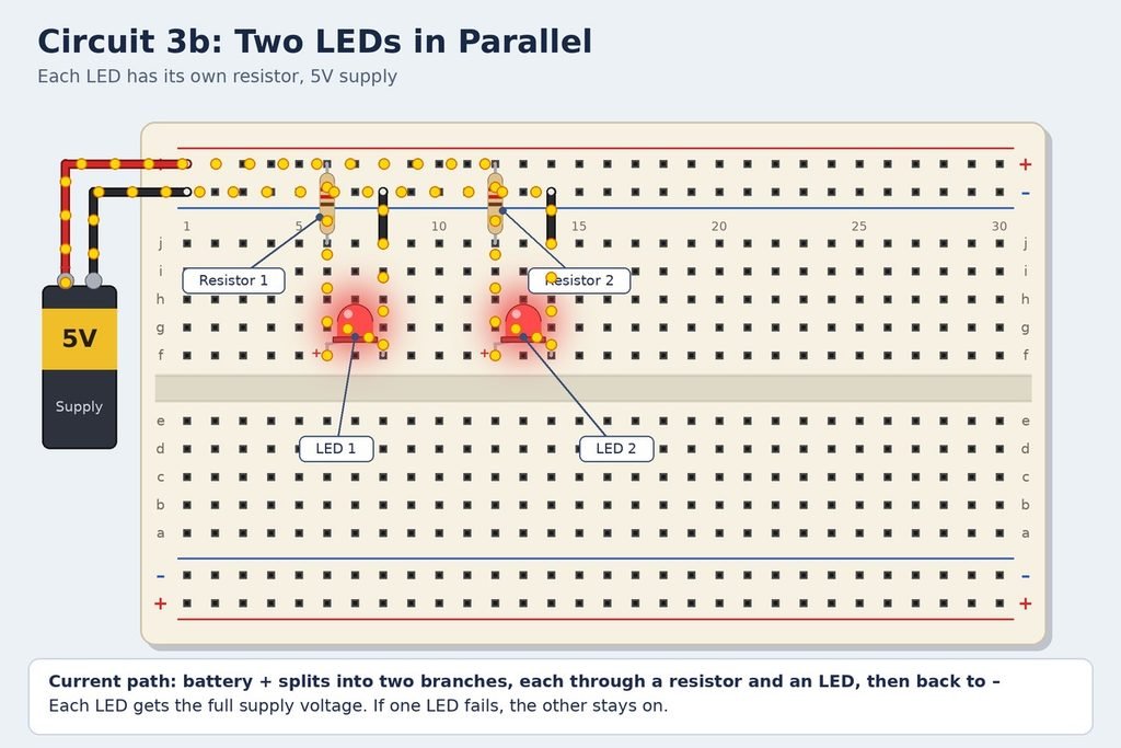
Parallel (side by side)
Give each LED its own resistor, and connect both branches between the red and blue rails. Each LED gets the full supply voltage, and if one fails the other stays on.
| Feature | Series | Parallel |
|---|---|---|
| Resistors needed | 1 | 1 per LED |
| If one LED fails | Both go off | Other stays on |
| Supply voltage | Higher | Lower |
Common mistakes to avoid
- Skipping the current-limiting resistor on an LED
- Connecting power with reversed polarity
- Using bent or damaged legs that make poor contact
- Building a messy circuit with long, tangled wires
- Forgetting that both power rails need a link to the supply
Safety tips
- Stay with low voltage (under 12V) while learning
- Disconnect power before changing the circuit
- Never use a breadboard with mains (wall) power
- Keep batteries away from loose metal wires
Frequently Asked Questions
Can I use a breadboard for permanent projects?
No. A breadboard is for testing. Once the circuit works, move it to a soldered board or PCB.
Why is my circuit not working?
Most problems come from a wrong column, a loose wire, or a backwards LED. Recheck every connection one by one.
Can a breadboard handle high current?
Not well. Most boards are best kept under about 1 A in total.
Do I need a multimeter?
It is not required, but it makes finding faults much easier.
What should I build next?
Try a blinking LED with a 555 timer, or add a sensor to switch a light.