
PCB Trace Width Calculator (IPC-2221)
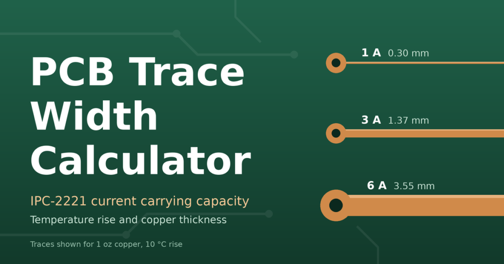
Work out the copper trace width you need for a given current, or the maximum current a trace can carry. The calculator uses the IPC-2221 current-carrying equation with your allowed temperature rise, copper thickness and layer type, then estimates resistance, voltage drop and power loss for your trace length.
Frequently Asked Questions
What is IPC-2221 and how does this calculator use it?
IPC-2221 is the generic standard for printed board design. It contains an empirical equation that relates current, temperature rise and copper cross-sectional area. This calculator solves that equation for trace width (or for current), then uses the copper thickness you choose to convert between area and width.
Why do internal traces need to be wider than external traces?
Internal traces are surrounded by laminate and cannot shed heat to the air as easily. IPC-2221 therefore uses a constant of 0.024 for internal layers versus 0.048 for external layers, which makes an internal trace roughly 2.6 times larger in cross-section for the same current and temperature rise.
What temperature rise should I choose?
A 10°C rise is a common, conservative default for general designs. 20–30°C is often acceptable when the board has thermal margin. Use a smaller rise for precision analog circuits, high ambient temperatures or products with long life requirements.
How does copper thickness affect trace width?
For a given current, the required cross-sectional area is fixed, so doubling the copper thickness halves the width. Standard weights are 0.5 oz (about 17 µm), 1 oz (about 35 µm), 2 oz (about 70 µm) and 3 oz (about 105 µm) per square foot.
Does trace length change the required width?
Not in the IPC-2221 heating equation. Length does set the resistance, voltage drop and power loss, so a long trace carrying high current may need to be wider than the thermal result to keep the voltage drop acceptable.
How accurate is the result?
IPC-2221 is based on older empirical charts and is generally conservative, especially for internal layers. The newer IPC-2152 standard accounts for board thickness, nearby copper planes and airflow. Treat this result as a solid starting point, and verify high-current or safety-critical designs with testing or thermal simulation.
Can I use this for vias, pulses or high-frequency signals?
No. The calculator assumes a steady DC current in a straight trace. Vias, short current pulses, skin effect at high frequency and controlled-impedance lines need separate calculations.