
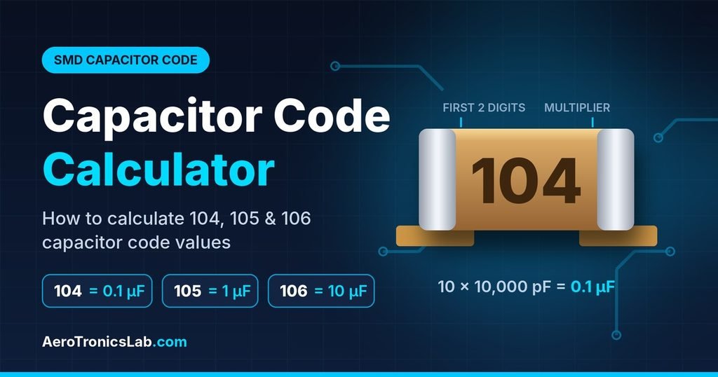
1. Introduction to SMD Capacitor Codes
SMD (Surface Mount Device) capacitors are widely used in modern electronic circuits, including smartphones, laptops, automotive electronics, industrial control systems, power supplies, communication equipment, and embedded systems.
Unlike traditional through-hole capacitors, SMD capacitors are designed to be mounted directly onto the surface of a Printed Circuit Board (PCB).
Some SMD capacitors use numerical markings such as 104, 105, 106, 103, and 224 to represent their capacitance values. Understanding these markings is important for electronics engineers, PCB designers, students, and technicians.
For example:
- 104 = 100,000 pF = 100 nF = 0.1 µF
- 105 = 1,000,000 pF = 1,000 nF = 1 µF
- 106 = 10,000,000 pF = 10,000 nF = 10 µF
- 103 = 10,000 pF = 10 nF = 0.01 µF
- 224 = 220,000 pF = 220 nF = 0.22 µF
An SMD Capacitor Code Calculator helps convert these numerical markings into actual capacitance values in picofarads (pF), nanofarads (nF), and microfarads (µF).
2. What Is an SMD Capacitor?
An SMD capacitor is an electronic component that stores electrical energy in an electric field. It is mounted directly onto a PCB without requiring component leads to pass through the board.
SMD capacitors are available in different sizes, capacitance values, voltage ratings, and dielectric materials.
Common Types of SMD Capacitors
| Capacitor Type | Description | Applications |
|---|---|---|
| MLCC Ceramic | Multilayer ceramic capacitor | Filtering and decoupling |
| Tantalum | Tantalum-based dielectric capacitor | Power supply filtering |
| Aluminium Electrolytic | Aluminium electrolytic construction | Power supply smoothing |
| Polymer Capacitor | Conductive polymer electrolyte | Low-ESR power circuits |
| Film Capacitor | Plastic film dielectric | Filtering and timing |
Note: Most small ceramic SMD capacitors do not have numerical markings printed on their bodies. Their values are generally identified using component packaging, BOMs, schematics, or datasheets.
3. Understanding the SMD Capacitor Code System
The three-digit capacitor code system is used to represent capacitance values in picofarads (pF).
The three digits have the following meaning:
- First digit: First significant digit.
- Second digit: Second significant digit.
- Third digit: Number of zeros to add, or multiplier.
SMD Capacitor Code Formula
Capacitance = First two digits × 10^(Third digit) pF
For example:
104 = 10 × 10⁴ pF
104 = 100,000 pF
104 = 100 nF = 0.1 µF
4. Detailed Example: How to Calculate a 104 Capacitor Value
The 104 marking is one of the most commonly encountered capacitor codes in electronics.
Let’s understand exactly what the 104 marking means.
Example 1: Identify a Capacitor Marked 104
Assume you have an SMD capacitor with the marking 104 printed on its body.
Step 1: Identify the three digits.
- First digit = 1
- Second digit = 0
- Third digit = 4
Step 2: Combine the first two digits.
10
Step 3: Apply the multiplier.
10 × 10⁴ = 10 × 10,000
Step 4: Calculate the capacitance.
10 × 10,000 = 100,000 pF
Step 5: Convert the value into nanofarads.
100,000 ÷ 1,000 = 100 nF
Step 6: Convert the value into microfarads.
100 ÷ 1,000 = 0.1 µF
Final Answer:
A capacitor marked 104 has a capacitance of:
- 100,000 pF
- 100 nF
- 0.1 µF
Example 2: Convert 104 Capacitor Value into Different Units
Given:
Capacitor marking = 104
Calculated capacitance = 100,000 pF
Conversion table:
| Unit | Calculation | Result |
|---|---|---|
| Picofarad (pF) | 10 × 10⁴ | 100,000 pF |
| Nanofarad (nF) | 100,000 ÷ 1,000 | 100 nF |
| Microfarad (µF) | 100,000 ÷ 1,000,000 | 0.1 µF |
| Farad (F) | 0.1 ÷ 1,000,000 | 0.0000001 F |
Example 3: Identify 104 Capacitor in a PCB Circuit
Consider a microcontroller circuit operating at 3.3 V.
A 104 capacitor (100 nF) is connected between the VDD and GND pins of the microcontroller.
Purpose:
- It helps suppress high-frequency power supply noise.
- It provides local charge during rapid switching activity.
- It helps stabilize the local supply voltage.
- It reduces noise coupled into the power supply network.
For example, an STM32 microcontroller PCB commonly uses 100 nF ceramic capacitors close to its power supply pins.
The capacitor should be placed close to the relevant supply and ground connections to minimize PCB parasitic inductance.
Example 4: Difference Between 104 and 105 Capacitors
Suppose you have two capacitors:
- Capacitor A = 104
- Capacitor B = 105
Calculate their values:
| Parameter | 104 Capacitor | 105 Capacitor |
|---|---|---|
| First two digits | 10 | 10 |
| Multiplier | 10⁴ | 10⁵ |
| Capacitance | 100,000 pF | 1,000,000 pF |
| Nanofarads | 100 nF | 1,000 nF |
| Microfarads | 0.1 µF | 1 µF |
The 105 capacitor has ten times the capacitance of the 104 capacitor.
5. SMD Capacitor Code Conversion Table
The following table shows commonly encountered three-digit capacitor codes and their capacitance values.
| Capacitor Code | Calculation | Capacitance (pF) | Capacitance (nF) | Capacitance (µF) |
|---|---|---|---|---|
| 100 | 10 × 10⁰ | 10 | 0.01 | 0.00001 |
| 101 | 10 × 10¹ | 100 | 0.1 | 0.0001 |
| 102 | 10 × 10² | 1,000 | 1 | 0.001 |
| 103 | 10 × 10³ | 10,000 | 10 | 0.01 |
| 104 | 10 × 10⁴ | 100,000 | 100 | 0.1 |
| 105 | 10 × 10⁵ | 1,000,000 | 1,000 | 1 |
| 106 | 10 × 10⁶ | 10,000,000 | 10,000 | 10 |
| 221 | 22 × 10¹ | 220 | 0.22 | 0.00022 |
| 222 | 22 × 10² | 2,200 | 2.2 | 0.0022 |
| 223 | 22 × 10³ | 22,000 | 22 | 0.022 |
| 224 | 22 × 10⁴ | 220,000 | 220 | 0.22 |
| 225 | 22 × 10⁵ | 2,200,000 | 2,200 | 2.2 |
| 331 | 33 × 10¹ | 330 | 0.33 | 0.00033 |
| 332 | 33 × 10² | 3,300 | 3.3 | 0.0033 |
| 333 | 33 × 10³ | 33,000 | 33 | 0.033 |
| 334 | 33 × 10⁴ | 330,000 | 330 | 0.33 |
| 471 | 47 × 10¹ | 470 | 0.47 | 0.00047 |
| 472 | 47 × 10² | 4,700 | 4.7 | 0.0047 |
| 473 | 47 × 10³ | 47,000 | 47 | 0.047 |
| 474 | 47 × 10⁴ | 470,000 | 470 | 0.47 |
| 475 | 47 × 10⁵ | 4,700,000 | 4,700 | 4.7 |
Note: These are mathematical interpretations of the three-digit picofarad code. Always verify the marking convention for the actual component.
6. SMD Capacitor Code Calculator – How to Calculate Capacitance
An SMD capacitor code calculator converts numerical capacitor markings into capacitance values automatically.
The calculator uses the three-digit code formula and displays the result in pF, nF, and µF.
How to Use the SMD Capacitor Calculator
- Identify the numerical marking on the capacitor.
- Enter the three-digit capacitor code into the calculator.
- Select the Calculate option.
- The calculator reads the first two digits as the significant value.
- The third digit determines the multiplier.
- The result is displayed in different capacitance units.
Calculator Input Examples
| Input Code | Capacitance (pF) | Capacitance (nF) | Capacitance (µF) |
|---|---|---|---|
| 103 | 10,000 | 10 | 0.01 |
| 104 | 100,000 | 100 | 0.1 |
| 105 | 1,000,000 | 1,000 | 1 |
| 106 | 10,000,000 | 10,000 | 10 |
| 224 | 220,000 | 220 | 0.22 |
| 334 | 330,000 | 330 | 0.33 |
| 474 | 470,000 | 470 | 0.47 |
| 475 | 4,700,000 | 4,700 | 4.7 |
7. Difference Between pF, nF, and µF
Capacitance is measured in Farads (F). Smaller units are commonly used in electronic circuits.
| Unit | Equivalent Value |
|---|---|
| 1 Farad (F) | 1,000,000 µF |
| 1 µF | 1,000 nF |
| 1 µF | 1,000,000 pF |
| 1 nF | 1,000 pF |
| 1 pF | 0.001 nF |
| 1 pF | 0.000001 µF |
Important Conversion Formulas
Picofarads to Nanofarads:
nF = pF ÷ 1,000
Nanofarads to Microfarads:
µF = nF ÷ 1,000
Picofarads to Microfarads:
µF = pF ÷ 1,000,000
Microfarads to Picofarads:
pF = µF × 1,000,000
8. Common SMD Capacitor Values Used in Electronic Circuits
Different capacitor values are used for filtering, decoupling, timing, noise suppression, and power supply applications.
| Capacitance | Common Application | Example |
|---|---|---|
| 10 pF | Crystal oscillator circuits | Oscillator load |
| 22 pF | Crystal oscillator circuits | MCU clock circuit |
| 100 pF | High-frequency filtering | RF circuits |
| 1 nF | Noise filtering | Signal conditioning |
| 10 nF | Bypass and filtering | Analog circuits |
| 100 nF | Decoupling | Microcontroller VDD |
| 1 µF | Power supply filtering | LDO input/output |
| 4.7 µF | Power supply stabilization | DC-DC converter |
| 10 µF | Bulk decoupling | Power rails |
| 47 µF | Energy storage and smoothing | Power supplies |
9. SMD Capacitor Package Sizes
SMD capacitors are available in different physical package sizes. Package size does not directly indicate capacitance.
| Package Size (Imperial) | Metric Size | Typical Applications |
|---|---|---|
| 0201 | 0603 | Miniature electronics |
| 0402 | 1005 | Mobile and compact PCB |
| 0603 | 1608 | General electronics |
| 0805 | 2012 | Industrial electronics |
| 1206 | 3216 | Power supply circuits |
| 1210 | 3225 | Higher capacitance applications |
| 1812 | 4532 | Larger capacitance applications |
10. Important Parameters to Check When Selecting SMD Capacitors
Identifying capacitance is only one part of capacitor selection. Engineers must also consider electrical and physical parameters.
| Parameter | Description | Importance |
|---|---|---|
| Capacitance | Stored charge capability | Circuit performance |
| Voltage Rating | Maximum specified working voltage | Prevents overstress |
| Tolerance | Permitted capacitance variation | Accuracy |
| Dielectric Type | C0G, X7R, X5R, etc. | Stability |
| ESR | Equivalent Series Resistance | Power circuit performance |
| ESL | Equivalent Series Inductance | High-frequency performance |
| Temperature Range | Operating temperature limits | Reliability |
| Package Size | Physical dimensions | PCB footprint |
Common Ceramic Capacitor Dielectrics
| Dielectric | Characteristics | Applications |
|---|---|---|
| C0G / NP0 | Excellent stability and low losses | Oscillator and precision circuits |
| X7R | General-purpose stability | Decoupling and filtering |
| X5R | High capacitance in compact packages | Power supply filtering |
| Y5V | High capacitance density but poor stability | Less demanding applications |
Important: X7R and X5R capacitors can experience capacitance reduction under DC bias. Always check the manufacturer’s DC bias characteristics.
11. Common Mistakes When Reading SMD Capacitor Codes
| Mistake | Incorrect Interpretation | Correct Interpretation |
|---|---|---|
| Misreading 104 | 104 pF | 100 nF |
| Confusing nF and µF | 100 nF = 100 µF | 100 nF = 0.1 µF |
| Ignoring multiplier | 224 = 224 pF | 224 = 220 nF |
| Assuming all SMD capacitors are marked | All have printed codes | Many MLCCs are unmarked |
| Ignoring voltage rating | Capacitance alone is enough | Check voltage rating |
| Ignoring dielectric | All 100 nF capacitors behave identically | Dielectric affects performance |
12. Frequently Asked Questions (FAQ)
1. What is the value of a 104 SMD capacitor?
A capacitor marked 104 has a capacitance of 100,000 pF, equivalent to 100 nF or 0.1 µF.
2. What does 104 mean on a capacitor?
The first two digits represent 10, and the third digit represents a multiplier of 10⁴. Therefore, 10 × 10⁴ = 100,000 pF.
3. How do I calculate a 104 capacitor value?
Use the formula:
Capacitance = 10 × 10⁴ pF
Result = 100,000 pF = 100 nF = 0.1 µF.
4. What is the value of a 105 capacitor?
105 represents 1,000,000 pF, equivalent to 1,000 nF or 1 µF.
5. What is the value of a 106 capacitor?
106 represents 10,000,000 pF, equivalent to 10,000 nF or 10 µF under the standard three-digit pF code.
6. What is the difference between 103 and 104 capacitors?
103 = 10 nF = 0.01 µF.
104 = 100 nF = 0.1 µF.
The 104 capacitor has ten times the capacitance of the 103 capacitor.
7. What is the value of a 224 capacitor?
224 represents 220,000 pF, equivalent to 220 nF or 0.22 µF.
8. What is the value of a 474 capacitor?
474 represents 470,000 pF, equivalent to 470 nF or 0.47 µF.
9. Can I replace a 104 capacitor with a 105 capacitor?
Not directly in most applications. A 104 capacitor is 100 nF, while a 105 capacitor is 1 µF. The replacement changes capacitance by a factor of ten. Always check the circuit requirements.
10. Do all SMD capacitors have numerical markings?
No. Most small multilayer ceramic capacitors do not have printed markings. Their capacitance values are identified using component packaging, BOMs, schematics, or datasheets.
11. What is the most commonly used SMD capacitor value?
100 nF (0.1 µF), represented by code 104 in the three-digit coding system, is commonly used for decoupling and bypass applications.
12. What voltage rating should I choose for an SMD capacitor?
Choose a voltage rating appropriate for the circuit’s maximum operating voltage, transient conditions, and derating requirements. Also consider DC bias effects for ceramic capacitors.
13. How can I identify an unmarked SMD capacitor?
Use the PCB schematic, BOM, manufacturer part number, datasheet, or an appropriate LCR meter. Measuring a capacitor in-circuit can produce inaccurate results because of parallel components.
14. What happens if I use the wrong capacitor value?
Using an incorrect capacitance value can affect filtering, timing, power supply stability, noise performance, and circuit operation.
15. What is the difference between 104 and 100nF?
There is no capacitance difference when 104 is used as the standard three-digit pF code. Both represent 100 nF or 0.1 µF.
13. Conclusion
Understanding SMD capacitor codes is an important skill for electronics students, PCB designers, hardware engineers, and technicians.
The three-digit coding method makes it easy to calculate capacitance values from component markings.
The most important capacitor codes to remember are:
| Capacitor Code | Capacitance |
|---|---|
| 102 | 1 nF |
| 103 | 10 nF |
| 104 | 100 nF (0.1 µF) |
| 105 | 1 µF |
| 106 | 10 µF |
| 224 | 220 nF |
| 474 | 470 nF |
For example, when you identify a capacitor marked 104 on a PCB, you can calculate its value as 100 nF or 0.1 µF using the three-digit capacitor code formula.
Using an SMD Capacitor Code Calculator simplifies component identification and reduces calculation errors during PCB design, circuit development, and electronic troubleshooting.
Always verify the capacitance, voltage rating, tolerance, dielectric type, and manufacturer specifications before selecting a replacement component.
Suggested featured image: An SMD ceramic capacitor with a clearly visible 104 marking alongside a PCB, with the text “104 = 100nF = 0.1µF”.