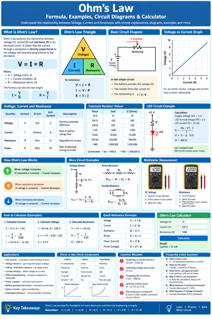
Ohm’s Law states that the current flowing through a conductor between two points is directly proportional to the voltage across those points and inversely proportional to the resistance between them. It is written as V = I × R, and it is the most important equation in basic electronics and electrical engineering.
This guide covers the Ohm’s Law formula, the formula triangle, units, a block diagram, circuit diagrams for series and parallel circuits, worked examples, a step-by-step how-to, applications, limitations and a detailed FAQ.
What is Ohm’s Law?
Ohm’s Law describes the relationship between three basic electrical quantities: voltage (V), current (I) and resistance (R). It was formulated by the German physicist Georg Simon Ohm (1789–1854), who published his findings in 1827. The SI unit of resistance, the ohm (Ω), is named in his honour.
In simple words, if resistance stays constant, doubling the voltage doubles the current. If voltage stays constant, doubling the resistance halves the current.
A helpful analogy is water flowing through a pipe. Voltage is the water pressure, current is the flow rate, and resistance is how narrow or blocked the pipe is. Higher pressure pushes more water through, and a narrower pipe lets less water through.
Ohm’s Law Formula and Formula Triangle
V = I × R
Where V is voltage in volts, I is current in amperes and R is resistance in ohms. Rearranging the equation gives the other two forms:
I = V ÷ R
R = V ÷ I
Ohm’s Law Formula Triangle
            V
        ---------
         I  |  R
Cover the quantity you want to find. If the remaining two are side by side (I and R), multiply them. If one is above the other (V over I, or V over R), divide the top by the bottom.
Quantities, Symbols and Units
| Quantity | Symbol | SI Unit | Unit Symbol | Measured With |
|---|---|---|---|---|
| Voltage (potential difference) | V | Volt | V | Voltmeter (in parallel) |
| Current | I | Ampere | A | Ammeter (in series) |
| Resistance | R | Ohm | Ω | Ohmmeter or multimeter |
| Power | P | Watt | W | Wattmeter |
| Conductance (1/R) | G | Siemens | S | Calculated |
Ohm’s Law Formula Variations
| To Find | Known Values | Formula |
|---|---|---|
| Voltage (V) | I and R | V = I × R |
| Current (I) | V and R | I = V ÷ R |
| Resistance (R) | V and I | R = V ÷ I |
| Power (P) | V and I | P = V × I |
| Power (P) | I and R | P = I² × R |
| Power (P) | V and R | P = V² ÷ R |
Common Unit Prefixes Used with Ohm’s Law
| Prefix | Symbol | Multiplier | Example |
|---|---|---|---|
| Mega | M | 1,000,000 | 2 MΩ = 2,000,000 Ω |
| Kilo | k | 1,000 | 4.7 kΩ = 4,700 Ω |
| Milli | m | 0.001 | 20 mA = 0.02 A |
| Micro | µ | 0.000001 | 50 µA = 0.00005 A |
Ohm’s Law Block Diagram
The block diagram below shows how the three quantities interact in a simple circuit. The voltage source drives current through the load, and the load’s resistance determines how much current flows.
+----------------+   applies V   +----------------+   limits I   +--------------------+
| Voltage Source | ------------> | Resistive Load | -----------> |    Current Flow    |
|  V (volts)     |               |  R (ohms)      |              | I = V ÷ R (amperes)|
+----------------+               +----------------+              +--------------------+

                         Ohm's Law: V = I × R
Basic Ohm’s Law Circuit Diagram
The simplest circuit that demonstrates Ohm’s Law is a DC battery connected across a single resistor. In this example, a 12 V battery is connected to a 4 Ω resistor.
        I = 3 A
     ------>
 +-----------/\/\/\/\-----------+
 |           R = 4 Ω            |
 |                              |
_|_ +                           |
___  12 V                       |
 |  -                           |
 |                              |
 +------------------------------+
Using Ohm’s Law: I = V ÷ R = 12 ÷ 4 = 3 A
V-I Characteristics Graph of Ohm’s Law
When voltage is plotted against current for an ohmic conductor (such as a metal wire or a resistor at constant temperature), the result is a straight line through the origin. The slope of the line gives the resistance. A non-ohmic device, such as a diode, produces a curve instead.
| Voltage (V) | Current (A) through a 4 Ω resistor |
|---|---|
| 0 | 0 |
| 4 | 1 |
| 8 | 2 |
| 12 | 3 |
| 16 | 4 |
The current increases in equal steps as the voltage increases, which confirms that the relationship is linear.
Ohm’s Law in Series and Parallel Circuits
Series Circuit
In a series circuit, the same current flows through every resistor. The total resistance is the sum of all resistances, and the supply voltage divides across them.
R total = R1 + R2 + R3
I = V ÷ R total
V total = V1 + V2 + V3
 +-----/\/\/\-----/\/\/\-----/\/\/\-----+
 |     R1=10Ω      R2=20Ω     R3=30Ω    |
 |                                       |
_|_ +                                    |
___ 12 V                                 |
 |  -                                    |
 +---------------------------------------+
R total = 10 + 20 + 30 = 60 Ω
I = 12 ÷ 60 = 0.2 A (the same through all resistors)
Voltage drops: V1 = 2 V, V2 = 4 V, V3 = 6 V (total 12 V)
Parallel Circuit
In a parallel circuit, every branch has the same voltage across it, and the total current is the sum of the branch currents. The total resistance is always less than the smallest branch resistance.
1/R total = 1/R1 + 1/R2 + 1/R3
I total = I1 + I2 + I3
 +--------+------------+
 |        |            |
 |      /\/\/\       /\/\/\
_|_ +   R1=100Ω     R2=100Ω
___ 10 V   |            |
 |  -      |            |
 +--------+------------+
R total = (100 × 100) ÷ (100 + 100) = 50 Ω
I total = 10 ÷ 50 = 0.2 A (0.1 A in each branch)
Series vs Parallel Comparison
| Property | Series Circuit | Parallel Circuit |
|---|---|---|
| Current | Same through all components | Divides among branches |
| Voltage | Divides across components | Same across all branches |
| Total resistance | R1 + R2 + R3 | 1/R1 + 1/R2 + 1/R3 (reciprocal) |
| If one component fails | Entire circuit stops | Other branches keep working |
| Typical use | Voltage dividers, LED strings | Household wiring, power outlets |
Ohm’s Law and the Power Formulas
Electrical power is the rate at which energy is used. Combining Ohm’s Law with P = V × I gives three useful forms:
P = V × I
P = I² × R
P = V² ÷ R
These formulas are essential when choosing a resistor’s wattage rating. A resistor that dissipates more power than its rating will overheat and fail.
Ohm’s Law Wheel (Complete Formula Table)
| Find | Using V and I | Using V and R | Using I and R | Using P and one other |
|---|---|---|---|---|
| V | – | – | I × R | P ÷ I or √(P × R) |
| I | – | V ÷ R | – | P ÷ V or √(P ÷ R) |
| R | V ÷ I | – | – | V² ÷ P or P ÷ I² |
| P | V × I | V² ÷ R | I² × R | – |
How to Apply Ohm’s Law (Step by Step)
- Draw the circuit. Sketch the source, resistors and connections, and label every known value with its unit.
- Identify the unknown. Decide whether you need voltage, current, resistance or power.
- Convert units. Change mA to A and kΩ to Ω before calculating. For example, 20 mA = 0.02 A.
- Simplify the circuit. Add series resistors. Combine parallel resistors using the reciprocal formula to get one equivalent resistance.
- Choose the right formula. Use the formula triangle: V = I × R, I = V ÷ R or R = V ÷ I.
- Substitute and calculate. Put in the values and solve, keeping track of units.
- Check the power. Calculate P = I² × R to confirm each resistor’s wattage rating is high enough.
- Verify with a multimeter. Measure voltage across the component (in parallel) and current through it (in series) to confirm your result.
Solved Examples
Example 1: Finding Current
A 9 V battery is connected across a 450 Ω resistor. Find the current.
I = V ÷ R = 9 ÷ 450 = 0.02 A (20 mA)
Example 2: Finding Voltage
A current of 2 A flows through a 15 Ω heating element. Find the voltage across it.
V = I × R = 2 × 15 = 30 V
Example 3: Finding Resistance
A device draws 0.5 A when connected to a 230 V supply. Find its resistance.
R = V ÷ I = 230 ÷ 0.5 = 460 Ω
Example 4: LED Current-Limiting Resistor
An LED (forward voltage 2 V, desired current 20 mA) is powered from a 9 V supply. What resistor is needed?
Voltage across the resistor = 9 − 2 = 7 V
R = V ÷ I = 7 ÷ 0.02 = 350 Ω (nearest standard value: 360 Ω)
Power in the resistor = I² × R = 0.02² × 350 = 0.14 W, so a standard 0.25 W resistor is sufficient.
Example 5: Series Circuit
Three resistors of 10 Ω, 20 Ω and 30 Ω are connected in series across 12 V.
R total = 10 + 20 + 30 = 60 Ω
I = 12 ÷ 60 = 0.2 A
V1 = 0.2 × 10 = 2 V, V2 = 0.2 × 20 = 4 V, V3 = 0.2 × 30 = 6 V. These add up to 12 V.
Example 6: Parallel Circuit
Two 100 Ω resistors are connected in parallel across 10 V.
R total = (100 × 100) ÷ (100 + 100) = 50 Ω
I total = 10 ÷ 50 = 0.2 A, with 0.1 A in each branch.
Example 7: Power Calculation
A 12 V supply drives 3 A through a load.
P = V × I = 12 × 3 = 36 W
Practice Table: Find the Missing Value
| Voltage (V) | Current (I) | Resistance (R) | Answer |
|---|---|---|---|
| 5 V | ? | 1 kΩ | I = 5 mA |
| ? | 0.1 A | 220 Ω | V = 22 V |
| 24 V | 2 A | ? | R = 12 Ω |
| 3.3 V | ? | 330 Ω | I = 10 mA |
Applications of Ohm’s Law
- LED circuits: calculating current-limiting resistors so LEDs do not burn out.
- Voltage dividers: creating a lower reference voltage for sensors and microcontroller inputs.
- Electrical wiring: selecting wire gauge and fuse ratings to prevent overheating.
- Electric heaters and toasters: designing heating elements with the correct resistance.
- Power supply and battery design: estimating load current and runtime.
- Sensor and measurement circuits: shunt resistors for current measurement, and thermistors and strain gauges in bridge circuits.
- Troubleshooting: finding short circuits, open circuits and faulty components by comparing measured and calculated values.
- Education and PCB design: the foundation for circuit analysis, Kirchhoff’s laws and electronics design.
Limitations of Ohm’s Law
Ohm’s Law applies to ohmic materials at constant temperature. It does not hold for:
- Semiconductor devices such as diodes and transistors, whose V-I relationship is non-linear.
- Vacuum tubes and gas-discharge lamps.
- Components whose resistance changes with temperature, such as incandescent filaments and thermistors.
- AC circuits with reactive components, where impedance (Z) replaces simple resistance.
- Superconductors, which have zero resistance.
Frequently Asked Questions (FAQ) About Ohm’s Law
What is Ohm’s Law in simple words?
Ohm’s Law says that the current through a conductor is proportional to the voltage across it and inversely proportional to its resistance. The formula is V = I × R.
What is the formula for Ohm’s Law?
The formula is V = I × R. Rearranged, I = V ÷ R and R = V ÷ I, where V is voltage in volts, I is current in amperes and R is resistance in ohms.
Who discovered Ohm’s Law?
German physicist Georg Simon Ohm discovered the relationship and published it in 1827. The unit of electrical resistance, the ohm (Ω), is named after him.
What is the unit of resistance?
The SI unit of resistance is the ohm (symbol Ω). One ohm is the resistance that allows one ampere of current to flow when one volt is applied across it.
What is the Ohm’s Law triangle?
The Ohm’s Law triangle is a memory aid with V on top and I and R at the bottom. Cover the quantity you want to find. If the other two are side by side, multiply them. If one is above the other, divide.
Is Ohm’s Law valid for AC circuits?
Yes, with a modification. For purely resistive AC circuits, V = I × R holds for instantaneous and RMS values. For circuits with inductors and capacitors, resistance is replaced by impedance (Z), giving V = I × Z.
Why does Ohm’s Law not apply to diodes?
A diode’s resistance changes with the applied voltage, so its V-I graph is a curve rather than a straight line. Such devices are called non-ohmic.
How do you calculate power using Ohm’s Law?
Combine Ohm’s Law with P = V × I to get P = I² × R and P = V² ÷ R. For example, a 12 V supply driving 3 A delivers 36 W.
What happens to current if resistance increases?
If the voltage stays constant, current decreases when resistance increases. Doubling the resistance halves the current.
How do I measure voltage, current and resistance with a multimeter?
Measure voltage by connecting the meter in parallel across the component. Measure current by connecting the meter in series with the circuit. Measure resistance with the power off and the component isolated from the circuit.
What is the difference between Ohm’s Law and Kirchhoff’s Laws?
Ohm’s Law relates voltage, current and resistance for a single component. Kirchhoff’s Current Law and Voltage Law describe how currents and voltages behave at junctions and around loops in a complete circuit. They are used together to analyse complex networks.
What is the relationship between conductance and Ohm’s Law?
Conductance (G) is the reciprocal of resistance: G = 1 ÷ R, measured in siemens (S). Ohm’s Law can then be written as I = G × V.
Conclusion
Ohm’s Law (V = I × R) is the foundation of electronics. Once you understand how voltage, current and resistance relate, you can design LED circuits, size resistors, analyse series and parallel networks, calculate power and troubleshoot real circuits with confidence.
Key Takeaways
- Ohm’s Law: V = I × R, with I = V ÷ R and R = V ÷ I.
- Current increases with voltage and decreases with resistance.
- Series: same current, voltages add. Parallel: same voltage, currents add.
- Power: P = V × I = I² × R = V² ÷ R.
- Ohm’s Law applies to ohmic materials. Diodes and transistors are non-ohmic.