A resistor is a passive two-terminal electrical component designed to implement electrical resistance in a circuit. In simple terms, a resistor limits or controls the flow of electrical current (electrons) passing through a circuit, much like a narrow pipe restricts the flow of water.
Resistors are fundamental elements in almost every electronic circuit, used to adjust signal levels, divide voltages, bias active elements, and terminate transmission lines.
How Does a Resistor Work?
Resistors work based on the principle of collision at the atomic level. When a voltage source is applied across a conductor or resistive material, electrons begin to flow. As these electrons move through the material, they collide with atoms and impurities within the resistive element. These collisions impede electron flow and dissipate excess electrical energy in the form of heat.
Schematic Symbols and Block Diagram
In circuit diagrams, resistors are represented using standardized symbols depending on the regional standard (IEEE/US vs. IEC/Europe).
Circuit Symbols Representation
- IEEE/ANSI Symbol (North America): Represented by a zig-zag line.
- IEC Symbol (Europe/International): Represented by a simple rectangular box.
- Variable Resistor Symbol: Contains an arrow drawn through or pointing toward the symbol to indicate adjustability.
Structural Block Diagram
Below is the conceptual block breakdown of a standard axial carbon film resistor:
[ Lead Terminal ] ---> [ Resistive Element (Carbon Film) ] <--- [ Lead Terminal ]
                                  |
                   [ Ceramic Insulating Substrate ]
                                  |
                   [ Protective Epoxy Coating ]
Key Formulas and Working Equations
The primary physical law governing resistors is Ohm’s Law, which defines the relationship between Voltage (V), Current (I), and Resistance (R).
Ohm’s Law Equation
- Voltage: V = I * R
- Current: I = V / R
- Resistance: R = V / I
(Where V is measured in Volts, I in Amperes, and R in Ohms).
Power Dissipation Equation
Resistors convert excess electrical energy into heat. Power rating determines how much power a resistor can safely handle without damage.
- Power (P): P = V * I
- Alternative Power Formulas: P = I^2 * R OR P = V^2 / R
(Where P is measured in Watts).
Types of Resistors
Resistors are broadly classified into two categories: Fixed Resistors and Variable Resistors.
| Resistor Type | Category | Core Characteristics | Primary Applications |
|---|---|---|---|
| Carbon Film | Fixed | Low cost, moderate precision | General-purpose consumer electronics |
| Metal Film | Fixed | High precision, low noise, high stability | Audio equipment, measurement instruments |
| Wirewound | Fixed | High power handling, high thermal stability | Power supplies, industrial machinery |
| Surface Mount (SMD) | Fixed | Compact chip design, low inductance | High-density PCBs, smartphones, laptops |
| Potentiometer | Variable | Manually adjustable 3-terminal control | Volume knobs, manual tuning |
| Thermistor (NTC/PTC) | Temperature Sensitive | Resistance changes drastically with temperature | Temperature sensors, overcurrent protection |
| Light Dependent (LDR) | Light Sensitive | Resistance decreases as light intensity increases | Automatic night lights, light meters |
Resistor Color Coding System
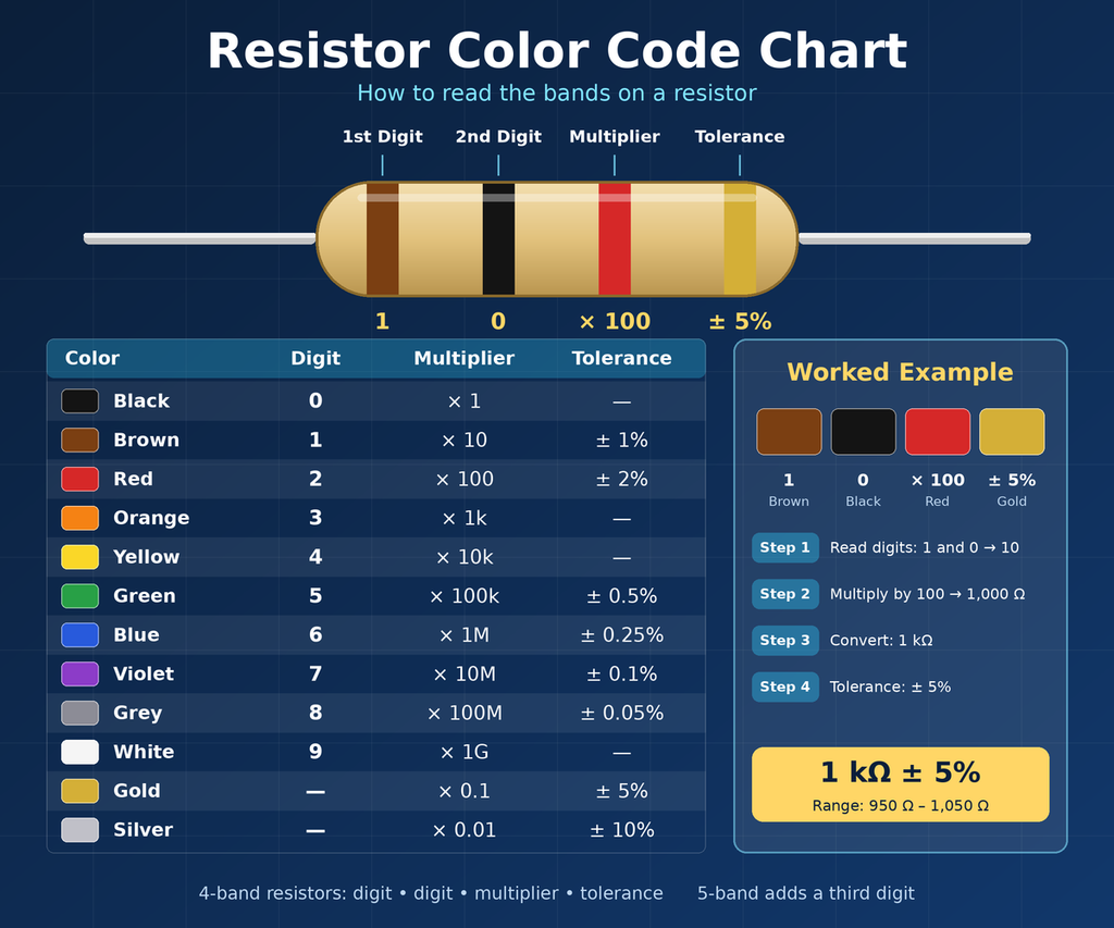
Axial resistors use color bands to indicate their resistance value, multiplier, and tolerance.
Color Code Reference Chart
| Color | Digit Value | Multiplier | Tolerance |
|---|---|---|---|
| Black | 0 | 10^0 (1) | – |
| Brown | 1 | 10^1 (10) | ±1% |
| Red | 2 | 10^2 (100) | ±2% |
| Orange | 3 | 10^3 (1K) | – |
| Yellow | 4 | 10^4 (10K) | – |
| Green | 5 | 10^5 (100K) | ±0.5% |
| Blue | 6 | 10^6 (1M) | ±0.25% |
| Violet | 7 | 10^7 (10M) | ±0.1% |
| Grey | 8 | 10^8 | ±0.05% |
| White | 9 | 10^9 | – |
| Gold | – | 0.1 | ±5% |
| Silver | – | 0.01 | ±10% |
Series vs Parallel Circuit Configurations
When combining multiple resistors in a circuit, total resistance changes based on connection topology.
1. Resistors in Series
Connecting resistors end-to-end increases overall path length, resulting in higher resistance.
- Formula: R_total = R1 + R2 + R3 + … + Rn
- Current: Current remains identical through all resistors.
- Voltage: Voltage drops across each individual resistor.
2. Resistors in Parallel
Connecting resistors across common nodes provides multiple parallel current paths, lowering overall resistance.
- Formula: 1 / R_total = (1 / R1) + (1 / R2) + (1 / R3) + … + (1 / Rn)
- Current: Total current splits across individual branches.
- Voltage: Voltage across each parallel branch remains identical.
Infographic Summary: What a Resistor Does
+-----------------------------------------------------------------------+
|                       RESISTOR SUMMARY INFOGRAPHIC                    |
+-----------------------------------------------------------------------+
|                                                                       |
|  FUNCTION         Ohm's Law: V = I * R                                |
|  ========         Restricts current flow and drops voltage.           |
|                                                                       |
|  UNIT             Ohm (Ω)                                             |
|  ====                                                                 |
|                                                                       |
|  MAIN TYPES       1. Fixed (Metal Film, Carbon, SMD)                  |
|  ==========       2. Variable (Potentiometer, Rheostat)               |
|                   3. Non-Linear (LDR, Thermistor, Varistor)           |
|                                                                       |
|  KEY ROLES        * Current Limiting (LED Protection)                 |
|  =========        * Voltage Division                                  |
|                   * Pull-Up / Pull-Down Resistors                     |
|                   * Signal Filtering (RC Networks)                    |
|                                                                       |
+-----------------------------------------------------------------------+
Frequently Asked Questions (FAQ)
What is the SI unit of resistance?
The standard SI unit of electrical resistance is the Ohm, denoted by the Greek letter Omega (Ω).
Why do resistors generate heat?
When current flows through a resistor, electrons collide with the internal material structure. This mechanical collision of moving charge carriers converts electrical energy into thermal energy.
What happens if a resistor fails?
Resistors generally fail in an open circuit state (burning out completely so no current flows). Less frequently, stress can cause a resistor to change value or fail short-circuit.
What is the difference between a resistor and an inductor?
A resistor opposes current flow by dissipating energy as heat. An inductor opposes changes in current by storing energy in a magnetic field.
How do I choose the correct power rating for a resistor?
Calculate expected power dissipation using P = I^2 * R. Always choose a resistor rated for at least twice the calculated power (50% derating rule) to prevent overheating.